Choosing an Optical Fiber Patch Cord is a small decision with network-wide consequences. A connector that fits loosely can create insertion loss, intermittent links, and expensive troubleshooting. In a crowded rack, one poorly routed cord may press against neighboring ports or exceed its bend radius. That detail matters.
Global connectivity demand keeps increasing. The International Telecommunication Union’s Facts and Figures 2023 reported that 5.4 billion people were online, representing about 67% of the world’s population. Cisco’s Annual Internet Report, covering 2018–2023, also projected continued growth in connected devices and network traffic. These trends place greater pressure on stable fiber infrastructure. Patch cords are not accessories anymore.
This guide presents seven practical tips for selecting the right Optical Fiber Patch Cord. It considers fiber mode, connector type, polish quality, cable construction, length, loss performance, and installation conditions. Standards such as TIA-568.3-D, IEC 61754, and IEC 61300 provide useful reference points for compatibility and testing. Manufacturer datasheets still require careful checking. They are not always equally detailed.
Technicians commonly inspect end faces with a fiber microscope before connecting them. Dust can remain invisible until signal loss appears. A short bend near an LC connector can also weaken performance over time. Cleaning is essential.
Reports from the Fiber Broadband Association and TeleGeography show continued investment in fiber access and international bandwidth. However, choosing by price alone remains a risky habit. A cheaper cord may use weaker jackets, inconsistent connectors, or incomplete test documentation. That assumption deserves review. The best choice balances application requirements, verified test results, safety, and long-term maintainability.

Identify the fiber type before comparing prices or connector shapes. Single-mode fiber suits long distances and high-capacity links, often using 1310 nm or 1550 nm wavelengths. Multimode fiber fits shorter links inside buildings, with common options such as OM3, OM4, and OM5. Check the installed cable label, transceiver specification, and network design documents. Do not guess. A mismatch can cause unstable links, excessive loss, or complete failure. Confirm the required data rate and transmission distance, then compare the cord’s attenuation and return-loss limits with those requirements. A short cord still matters. Its loss adds to the entire channel budget.
Connector performance deserves equal attention. Verify the connector interface, polish type, simplex or duplex arrangement, and required polarity. Inspect the end face for dust under a fiber microscope, and clean it before connection. I have seen clean-looking connectors fail after repeated handling. That mistake is easy to make. Choose cords with documented test results, suitable bend-radius protection, and a jacket rated for the installation area. For rack connections, measure the routing path rather than estimating it. Excess length creates loops, while insufficient length strains the connector. Standards-based testing, traceable measurements, and clear labeling improve reliability. Still, specifications can be misunderstood, so review the final selection with the network installer before deployment.

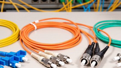
Choosing an optical fiber patch cord starts with the equipment, not the cable’s appearance. Identify the connector on each port, then verify its gender, keying, and fiber count. Common interfaces include LC, SC, ST, and MPO-style multifiber connectors. An adapter accepts only a matching connector format. A small mismatch can stop an installation.
Polishing style affects insertion loss and back reflection. UPC end faces suit many standard data links, while APC polishing reduces reflected light in sensitive single-mode applications. Never mate unlike polishing styles. The angled end needs the correct adapter and alignment. Inspect both end faces with a scope before connection, and clean them with approved lint-free tools. Dust is tiny. Its effect is not.
Check the adapter interface inside the panel, transceiver, or wall outlet. An LC duplex adapter, for example, requires correct polarity and latch orientation. MPO systems demand attention to key position, pin configuration, and polarity method. Confirm the fiber mode, core size, jacket rating, and required length against the link design. I once treated connector labels as sufficient; they were not. Documentation can be incomplete, so compare the physical port with the specification sheet. Leave gentle service slack, avoid tight bends, and record the tested loss for future troubleshooting.
Match the cable construction to the installation path. Simple duplex cords suit short rack connections. Armored cords offer extra protection in exposed areas. Indoor trunks need different strength members from outdoor assemblies. I once selected a tight-buffered cord for a crowded cabinet. It worked, but routing became unnecessarily difficult. Measure the pathway before ordering.
Treat jacket material as a safety and environment decision. PVC jackets are flexible and economical for many indoor spaces. LSZH jackets can reduce smoke and corrosive gases during a fire. Outdoor cables may require sunlight, moisture, and temperature resistance. Check the jacket rating against the installation location, not just the price. Read the datasheet carefully. Small wording differences matter.
Protect performance through handling details. Confirm the fiber mode, connector polish, and required bend radius. A cable can meet its specification and still fail after a sharp bend. Keep patch cords away from hinges, hot equipment, and crushed cable managers. Clean connectors before testing them. Always test insertion loss when the link is critical. Visual inspection is useful, but it is not enough. My own field checks have shown that “looks fine” can be misleading.
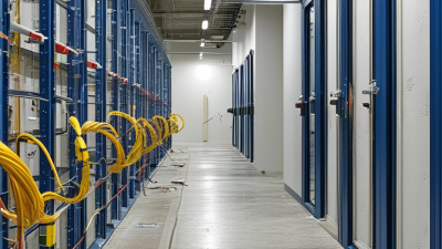
A patch cord that is too short can pull against connector housings. One that is too long creates loose coils and accidental bends. Measure the real path, including cabinet depth, routing changes, and a small service loop. The Fiber Optic Association recommends controlled slack rather than tight storage. I usually leave enough room for maintenance, but not enough for large loops behind the rack. It is an easy detail to misjudge.
Bend radius deserves closer attention. ANSI/TIA-568.3-E installation guidance commonly uses ten times the cable diameter without pulling tension and twenty times during movement or pulling. A 3-millimeter cord may therefore need about 30 millimeters of static radius. ITU-T G.657.A2 describes fiber performance at bend radii down to 7.5 millimeters, but that value applies to the fiber design, not automatically to the finished cord. I once treated those numbers as interchangeable. That was not careful engineering.
Environmental conditions can quietly change the selection. Check the rated temperature range, moisture exposure, ultraviolet light, vibration, and chemical contact. IEC 61753-1 defines connector performance categories under controlled environmental tests, helping buyers compare verified performance instead of attractive packaging. For outdoor cabinets, choose suitable jackets and sealing practices. For dense data rooms, confirm airflow and routing pressure. FOA field guidance often uses 0.3 dB as a practical target for one mated connector, so repeated reconnection and contamination deserve attention. A clean face still needs inspection.
A reliable optical fiber patch cord begins with verified quality. Check whether the supplier follows relevant IEC, ISO/IEC, or TIA requirements. Ask for batch-level test records, not only a general certificate. These records should show insertion loss, return loss, polarity, and fiber length.
End-face inspection is also essential. Dust can cause unstable links and permanent connector damage. Clean connectors before installation. Small details matter.
Compatibility requires careful checking. Match the fiber type, such as OS2, OM3, or OM4, with the installed network. Confirm the connector interface, polish type, jacket material, and required length.
Duplex polarity must suit the equipment and cabling method. I once ordered cords with the correct connectors but the wrong polarity. The link failed until every pair was traced manually.
That mistake cost more than the original price difference.
Total cost includes more than the purchase invoice. Include testing, cleaning tools, installation time, spare cords, and future replacement needs. A low-cost cord may have higher loss or weaker strain relief. It may also require earlier replacement.
Compare measured performance, warranty terms, packaging protection, and delivery reliability. Ask how the cords are tested before shipment.
Some suppliers provide detailed reports; others offer only verbal assurance. That should invite further checking, not immediate trust.